The Detailing Symbol Settings window ( Fabricator Settings )

The Detailing Symbol Settings window's settings are stored your current Fabricator . More than one Fabricator can be stored in a Job. Selecting a different Fabricator to be the active Fabricator in your current Job may result in this window being populated with a different collection of settings.

Also see :

page 1 | contents | home > project settings > fabricator > detailing > | classic


To open Detailing Symbol Settings :

Method 1 : Home > Project Settings > Fabricator > Detailing > Detailing Symbol Settings .

Methods 2, 3 & 4 : In Modeling or the Drawing Editor , choose Settings > Fabricator Settings > Detailing Symbol Settings (classic) or use a keyboard shortcut or click the icon .

Password protection: If a password has been set using the Change Setup Password utility, you can open this window only if you first enter that exact password.

page 1 | contents | home > project settings > fabricator > detailing > | classic | top


------ Options on this window ------

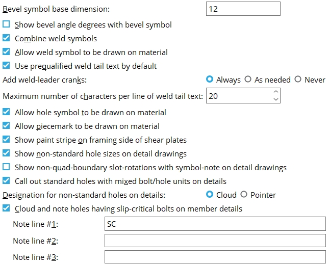
Bevel symbol base dimension: The distance (in the primary dimension " Units ") that is to be reported as the longer dimension (" Run " or " Rise ") on a bevel symbol or in the " Bevel " on the Distance Ruler window. If the " Rise " is longer than the " Run ," the value entered here is reported as the " Rise ." The default base dimension for ' Imperia l... ' dimensioning is ' 12 ' inches. For ' Metric ' dimensioning, the default is ' 250 ' mm. You can override the choice made here on a per-drawing basis by opening the drawing you want to change then applying the appropriate per-drawing setup override ( Settings > Drawing Settings > ... ), then saving your changes when you exit the drawing and then, the next time you detail members, selecting that member and detailing with templates .

Effect on drawings: The base dimension entered here applies to bevel symbols generated when you Detail Members or Detail Submaterial . It also applies to bevel symbols added using Add Bevel and to the " Bevel " reported on the " Angle " tab on the Distance Ruler window.

Per-drawing setup override for detailing with templates: " Bevel symbol base dimension "

Show bevel angle degrees with bevel symbol: or . The selection made here applies to all bevel symbols (except " Double-sided " bevel symbols) in all drawings that currently exist in your current Job as well as to yet-to-be-created drawings.

If the box is checked ( ), bevel angle degrees will be shown on bevel symbols .

If the box is not checked ( ), bevel angle degrees will not be shown on bevel symbols.

Combine weld symbols: or . The choice made here applies to weld symbols generated when you Detail Members . You can override the choice made here on a per-drawing basis by opening the drawing you want to change then applying the appropriate per-drawing setup override ( Settings > Drawing Settings > ... ), then saving your changes when you exit the drawing and then, the next time you detail members, selecting that member and detailing with templates .

Combine weld symbols

If this box is checked ( ), weld symbols that are in close proximity to one another and which each have a single pointer that designates the same weld to a different edge of material will be combined into a single weld symbol that points to those same edges with multiple pointers.

If the box is not checked ( ), weld symbols that are close to one another and which designate the same welds to different edges of materials will not be combined.

Per-drawing setup override for detailing with templates: " Combine weld symbols "

Allow weld symbol to be drawn on material: or . The choice made here applies to weld symbols generated when you Detail Members . You can override that choice on a per-drawing basis by opening the drawing you want to change then applying the appropriate per-drawing setup override ( Settings > Drawing Settings > ... ), then saving your changes when you exit the drawing and then, the next time you detail members, selecting that member and detailing with templates .

If this box is checked ( ), then on crowded details (where the weld symbol would otherwise have to be placed far away from the actual weld), auto detailing will instead place the weld symbol on the material.

If the box is not checked ( ), member detailing will not place the weld symbol on the material under any circumstances.

Per-drawing setup override for detailing with templates: " Allow weld symbol to be drawn on material "

Use prequalified weld tail text by default: or . The choice made here affects user-added welds that are created using Add Weld or Add Weld Layout in Modeling and, as a result, also affects whether or not prequalified tail text is shown for those welds on details. It also affects automatically detailed welds, but since there are no connection design routines that generate welds that would result in prequalified weld tail text being shown on the member detail, this option is, in effect, inconsequential for automatically detailed welds.

If this box is checked ( ), the box for " Use prequalified weld tail text " on the Add Weld window will be on (checked), by default, for welds that are subsequently added in Modeling .

If the box is not checked ( ), the box for " Use prequalified weld tail text " on the Add Weld window will be off (not checked), by default, for welds that are subsequently added in Modeling .

Add weld-leader cranks: Always or As needed . A weld-leader crank is a node or juncture near the pointer end of a weld leader line. The leader line may bend at the crank, or it may run straight across the crank. A crank on a straight leader line may be identified by an end point .

' Always ' instructs Detail Members to generate a crank at a point approximately the length of two arrow heads away from the tip of the arrow head at the end of a weld symbol's leader line. Even if the leader line is straight, a crank will be created, allowing you to manually bend the leader line at that juncture. Before v2015 versions of SDS2 software, all automatically detailed weld symbols had cranks.

' As needed ' instructs Detail Members to generate cranks only on weld symbols that have a bend near the tip of their pointers. Weld symbols with straight leader lines will not have cranks.

Maximum number of characters per line of weld tail text: This sets the default value for " Characters per line of symbol tail text " in the Weld Input window when you Detail Members. This value is the maximum length for a line of supplementary tail text measured by the number of characters. The text will wrap to the next line when this length is exceeded. The default value is 20. This value must be greater than or equal to 10 and less than or equal to 50. You can override the choice made here on a per-drawing basis by editing the weld symbol in Drawing Editor. Enter a different value in the " Characters per line of symbol tail text " field or check the box for " Keep layout symbol tail text as shown " on the Weld Input window.

Allow hole symbol to be drawn on material: or . This applies to hole symbols generated when you Detail Members . You can override the choice made here on a per-drawing basis by opening the drawing you want to change then applying the appropriate per-drawing setup override ( Settings > Drawing Settings > ... ), then saving your changes when you exit the drawing and then, the next time you detail members, selecting that member and detailing with templates .

If the box is checked ( ), then on crowded details (where the hole symbol would normally have to be placed far away from the actual hole), auto detailing will place the hole symbol (or slot symbol) on the material.

If the box is not checked ( ), member detailing will not place the hole symbol on the material under any circumstances.

Per-drawing setup override for detailing with templates: " Allow hole symbol to be drawn on material "

Allow piecemark to be drawn on material: or . This applies to piecemarks generated when you Detail Members . You can override the choice made here on a per-drawing basis by opening the drawing you want to change then applying the appropriate per-drawing setup override ( Settings > Drawing Settings > ... ), then saving your changes when you exit the drawing and then, the next time you detail members, selecting that member and detailing with templates .

If this box is checked ( ), then on crowded member details (where the submaterial mark would normally have to be placed far away from the material), auto detailing will place the piecemark on the material.

If the box is not checked ( ), member detaling will place the piecemark as close to the material as possible, but not on it.

Per-drawing setup override for detailing with templates: " Allow piecemark to be drawn on material "

Show paint stripe on framing side of shear plates: or . This applies when you Detail Members . You can override the choice made here on a per-drawing basis by opening the drawing you want to change then applying the appropriate per-drawing setup override ( Settings > Drawing Settings > ... ), then saving your changes when you exit the drawing and then, the next time you detail members, selecting that member and detailing with templates .

If the box is checked ( ), a no paint symbol will be drawn with a pointer to the framing side of the shear plate. This can be done as a means of communicating the framing side to erectors in the field.

If the box is not checked ( ), the no paint symbol is not drawn on subsequently generated member details.

Per-drawing setup override for detailing with templates: " Show paint stripe on framing side of shear plates "

Show non-standard hole sizes on detail drawings: or . This applies when you Detail Members . You can override the choice made here on a per-drawing basis by opening the drawing you want to change then applying the appropriate per-drawing setup override ( Settings > Drawing Settings > ... ), then saving your changes when you exit the drawing and then, the next time you detail members, selecting that member and detailing with templates . On submaterial details, non-standard hole sizes are always identified (regardless of your choice here).

Show non-standard ...

If the box is checked ( ), the diameter of non-standard holes will be noted on subsequently generated member details. Non-standard holes are slots or oversized holes or standard round holes for bolt diameters for bolt diameters other than the " Bolt diameter " for Non-moment bolts set in Bolt Settings .

If the box is not checked ( ), non-standard hole diameters will not be noted on automatically detailed member details.

Per-drawing setup override for detailing with templates: " Show non-standard hole sizes on detail drawings "

Show non-quad boundary slot-rotations with symbol-note on detail drawings: or . This applies when you Detail Members with " Show non-standard hole sizes on detail drawings " turned on. You can override the choice made here on a per-drawing basis by opening the drawing you want to change then applying the appropriate per-drawing setup override ( Settings > Drawing Settings > ... ), then saving your changes when you exit the drawing and then, the next time you detail members, selecting that member and detailing with templates .

Show symbol-note
Show symbol-note

If the box is checked ( ), slots that are called out with a slot symbol will also have their rotation called out if the slot has a non-quad boundary rotation. For typical non-rotated situations like that shown in the examples above, a non-quad boundary rotation is something other than ' 0 ' or ' 90 ' degrees. The rotation is recorded to the " Note text " on the Hole Symbol Input window.

If the box is not checked ( ), the rotation of a slot will not automatically be called out on with a note beneath its slot symbol.

Per-drawing setup override for detailing with templates: " Show non-quad boundary slot-rotations with symbol-note on detail drawings "

Call out standard holes with mixed bolt/hole units on details: or . This applies to member details when the primary dimensioning " Units " are different than the " Bolt diameter " set for Non-moment bolts in Bolt Settings . You can override the choice made here on a per-drawing basis by opening the drawing you want to change then applying the appropriate per-drawing setup override ( Settings > Drawing Settings > ... ), then saving your changes when you exit the drawing and then, the next time you detail members, selecting that member and detailing with templates .

 In this example, the primary dimensioning " Units " is ' Metric ' and the " Bolt diameter " is ' 3/4 ' inch.
Call out ...
Call out ...

Definition of standard hole: A standard hole is any round hole that is the standard diameter. SDS2 programs calculate the standard hole diameter from the " Bolt diameter " set for Non-moment bolts in Bolt Settings per Table J3.3 or Table J3.3M ( AISC Thirteenth Edition , p. 16.1-105).

If this box is checked ( ) and " Show non-standard hole sizes on detail drawings " is also checked, the diameter of a standard hole will be called out if it is in units that are different than the units of the " Bolt diameter " set in Bolt Settings . Hole units are different than bolt units when, for example, you have entered a " Bolt diameter " that is different than the primary dimensioning " Units " set in Drawing Presentation .

If the box is not checked ( ) and " Show non-standard hole sizes on detail drawings " is also checked, only non-standard holes will be called out. You might do this, for example, if you are in a metric Job and the fabricator uses an imperial-size punch to fabricate the standard holes.

Per-drawing setup override for detailing with templates: " Call out standard holes with mixed bolt/hole units on details "

Designation for non-standard holes on details: Cloud or Pointer . This applies to member details only. On submaterial details , non-standard hole sizes are always identified with clouds. The standard hole size for a Job is based on the default non-moment " Bolt diameter ." You can override the choice made here on a per-drawing basis by opening the drawing you want to change then applying the appropriate per-drawing setup override ( Settings > Drawing Settings > ... ), then saving your changes when you exit the drawing and then, the next time you detail members, selecting that member and detailing with templates .

Cloud
Pointer

Select ' Cloud ' if you want a cloud drawn around groups of non-standard holes.

Select ' Pointer ' if you want a pointer (->) drawn to indicate a non-standard hole group.

Per-drawing setup override for detailing with templates: " Designation for non-standard holes on details "

Cloud and note holes having slip-critical bolts on member details: or . You can override the choice made here on a per-drawing basis by opening the drawing you want to change then applying the appropriate per-drawing setup override ( Settings > Drawing Settings > ... ), then saving your changes when you exit the drawing and then, the next time you detail members, selecting that member and detailing with templates .

VIDEO In Home > Project Settings > Fabricator > Detailing Symbol Settings , a ' NO PAINT WITHIN 3 ' note is entered to " Note #1 " for slip critical bolts. (Recorded in SDS2 Detailing , v2016.)

The labels shown on this column detail were generated automatically during Detail Members based on entries made here. The entry made here to " Note line 1 " was ' SLIP CRITICAL '. The entry made here to " Note line 2 " was ' NO PAINT NS/FS '. " Note line 3 " was left blank.

If this box is checked ( ), then Detail Members clouds holes for slip-critical bolts and adds a callout consisting of a pointer and a label. The label consist of the " Note line 1 " text and " Note line 2 " text and " Note line 3 " text that is entered here. See the above example.

If the box is not checked ( ), Detail Members will not cloud and note holes for slip-critical bolts.

Per-drawing setup override for detailing with templates: " Cloud and note holes having slip-critical bolts on member details "

page 1 | contents | home > project settings > fabricator > detailing > | classic | top


To close Detailing Symbol Settings :

"OK" (or the Enter key) closes the Detailing Symbol Settings window and saves the settings on it to the current Fabricator . The settings may be applied in your current Job whenever that Fabricator is your current Fabricator. To change to a different Fabricator , Home > press "fabname" > double-click the Fabricator you want.

Note 1: If you make changes to the Detailing Symbol Settings window after automatic detailing has taken place, you will (in most cases) have to Detail Members and/or Detail Submaterial again in order for already existing details to be redrawn as you have specified here.

Note 2: If you checked or unchecked the box for " Show bevel angle degrees with bevel symbol ," automatic detailing is not required. Your change is seen in all the Drawing Editor drawings immediately.

"Cancel" (or the Esc key or the button) closes this window without saving any changes made to it.

"Reset" undoes all changes made to this window since you first opened it. The window remains open.

page 1 | contents | home > project settings > fabricator > detailing > | classic | top